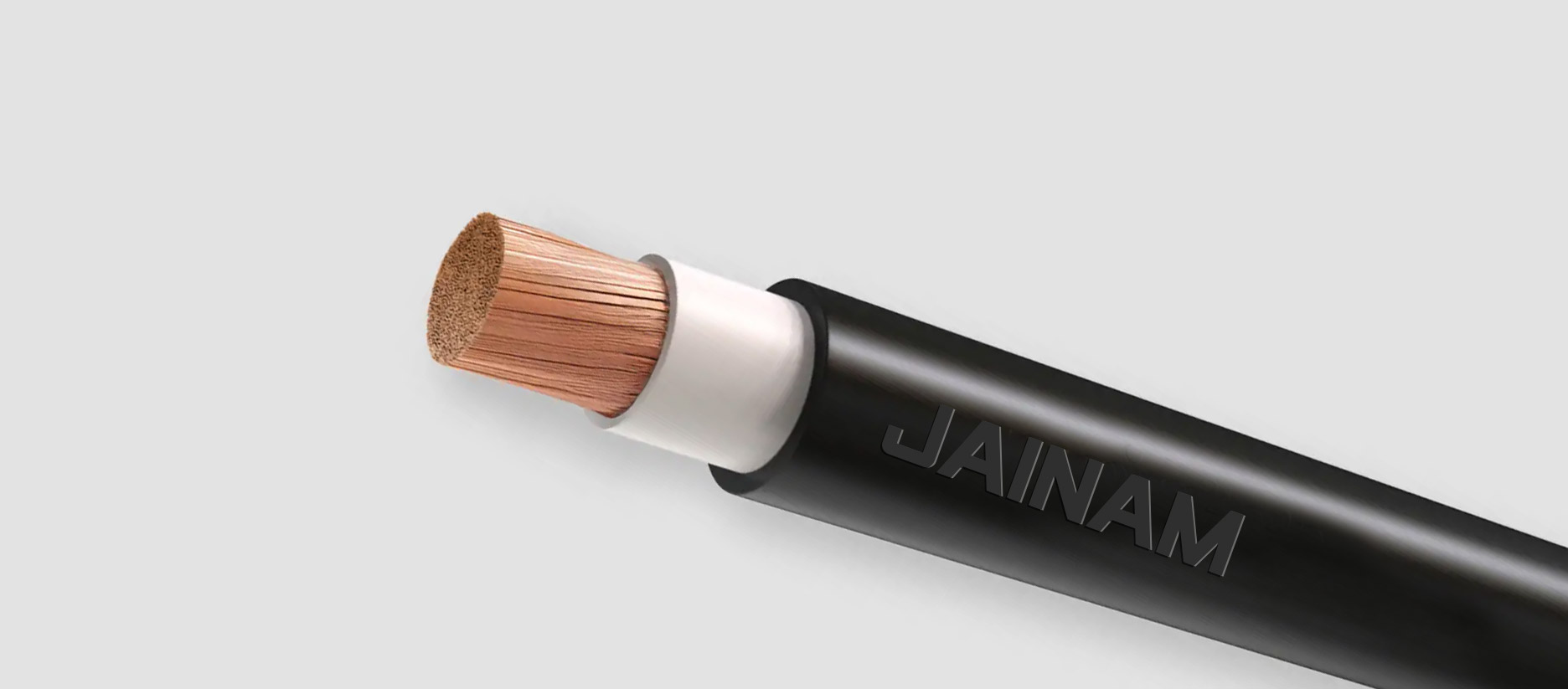
This extra-flex NBR welding cable features fine-stranded copper conductors and flexible insulation for smooth handling and robust performance in welding applications. Its excellent resistance to environmental and mechanical stresses ensures durability and long-term reliability. Ideal for connections between welding machines and electrode holders in industrial and fabrication settings.

Conductor : Welding Cable has a rope lay Class K stranded soft drawn bare copper conductor per ASTM B-172.
Separation : Polyester tape (25 to 30) Micron
Outer Sheath : NBR Double Sheath, black and oil resistant
*Any other Color on specific request can also be supplied
Fixed installation : -30°c to max.+ 90°C
Nominal voltage : 600V
Test voltage : 3000V
Mechnical Properties : Tensile strength = 10 N/mm2 Min.
Elongation = 300 Min.
Min. bending radius : 4 x cable diameter
Flame propagation : Flame retardant test as per IEC 60332-1
- Welding Cable is for use on connections from electrode holders and clamps to arc welders, bus welding box or transformers. Welding cable is for applications up to 600 volts and temperatures from -30°C to +90°C.
Standard length cable packing : Coils 100, 200, 300 and 500 m. in wooden reels
Ultra high performance flexible welding lead, double insulated for longer life and added safety
| Cross Sectional Area | Copper Construction | Nominal Thickness | Outer Dia Appx. | Max. Conductor Resistance at 20°C | Max. Current (Amb. Temp of 40°C) |
|---|---|---|---|---|---|
| AWG | Nos. / Dia. mm | mm | mm | Ω/km | AMPS |
| 6 | 273 / 0.254 | 8.00 | 10.70 | 1.39 | 115 |
| 4 | 427 / 0.254 | 9.50 | 12.10 | 0.873 | 150 |
| 2 | 651 / 0.254 | 11.00 | 14.20 | 0.554 | 205 |
| 1 | 817 / 0.254 | 11.70 | 15.40 | 0.44 | 240 |
| 1/0 | 1045 / 0.254 | 12.30 | 16.30 | 0.349 | 285 |
| 2/0 | 1330 / 0.254 | 14.40 | 18.70 | 0.276 | 325 |
| 3/0 | 1672 / 0.254 | 16.60 | 20.80 | 0.221 | 380 |
| 4/0 | 2146 / 0.254 | 18.20 | 23.00 | 0.175 | 440 |
| 250MCM | 2508 / 0.254 | 21.10 | 27.60 | 0.149 | 495 |
| 350MCM | 3496 / 0.254 | 20.80 | 30.80 | 0.106 | 680 |
| 500MCM | 5013 / 0.254 | 26.80 | 34.00 | 0.0743 | 720 |
| AMPS | 100' | 150' | 200' | 250' | 300' | 350' | 400' |
|---|---|---|---|---|---|---|---|
| 100 | 4 | 4 | 2 | 2 | 1 | 1/0 | 1/0 |
| 150 | 4 | 2 | 1 | 1/0 | 2/0 | 3/0 | 3/0 |
| 200 | 2 | 1 | 1/0 | 2/0 | 3/0 | 4/0 | 4/0 |
| 250 | 1 | 1/0 | 2/0 | 3/0 | 4/0 | ||
| 300 | 1/0 | 2/0 | 3/0 | 4/0 | |||
| 350 | 1/0 | 3/0 | 4/0 | ||||
| 400 | 2/0 | 3/0 | |||||
| 450 | 2/0 | 4/0 | |||||
| 500 | 3/0 | 4/0 | |||||
| 550 | 3/0 | 4/0 | |||||
| 600 | 4/0 |
The number of wires is approximate and wire diameter is nominal; they shall be such as to satisfy the requirements of conductor resistance of IEC 60228 / DIN VDE 0295 / IS 8130 / BS 6360
In view of continuous improvements in our design and process, specifications given here in are subject change without notice.